Network Rail Non-Station Footbridges: The Steel Is the Easy Part
Josh
5 Minute Read
Content
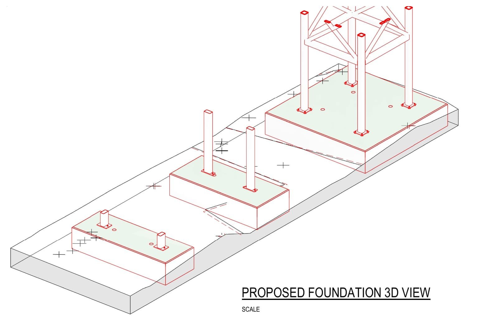
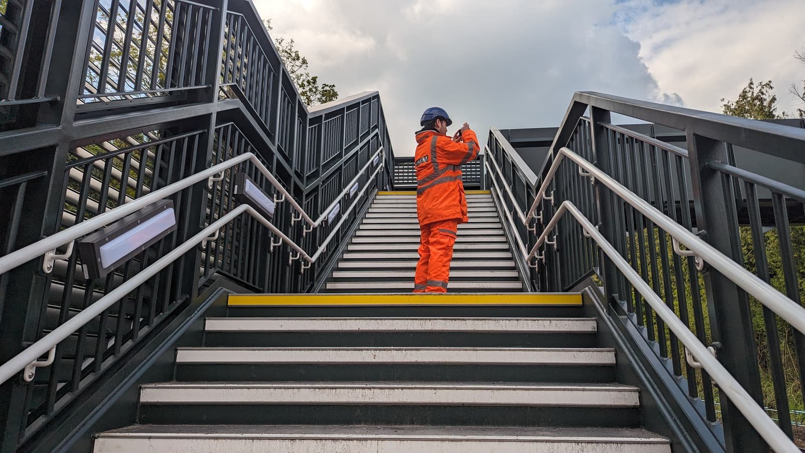
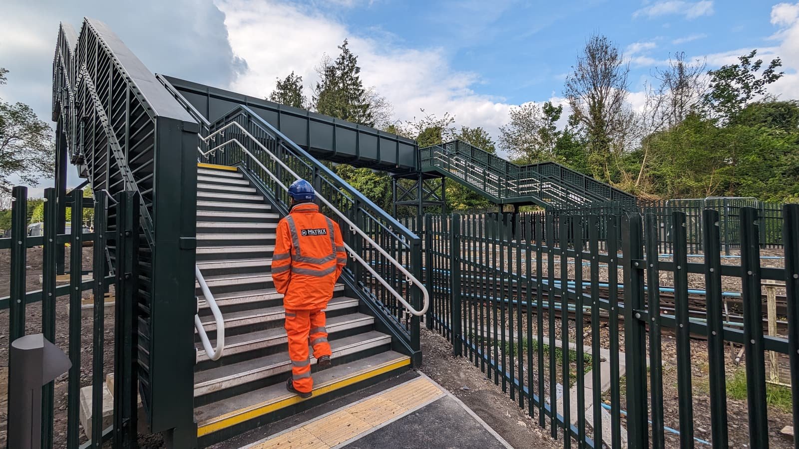
New Place should have been straightforward. A design-and-build replacement footbridge at a level crossing near Pulborough: 400-series standard details, Form A and Form B already signed by Network Rail, a superstructure the fabricator has built a dozen times. The steel was never the issue. What moved the programme was the ground. The bases needed resin-injection ground improvement before the tight settlement limits could be met, the technical queries went back to Network Rail, and the Form B submission had to wait, because a Form B on a standard footbridge still can’t go in until the one thing the standard details don’t cover, the foundation design, is closed out.
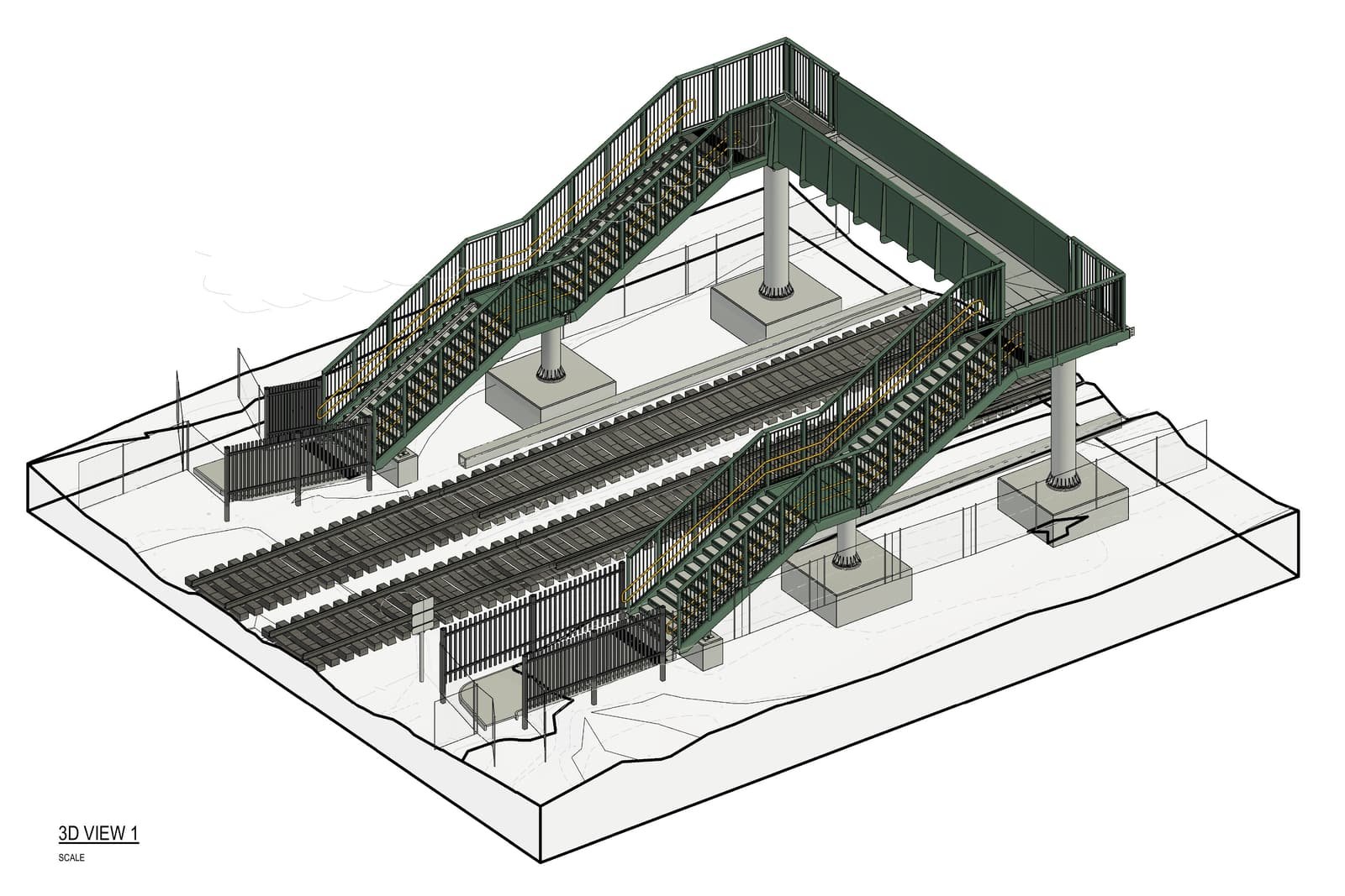
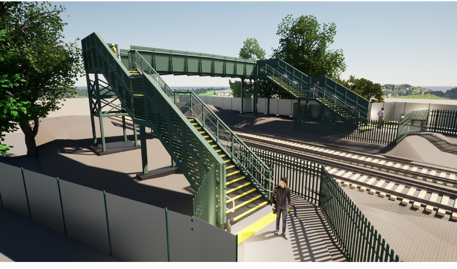
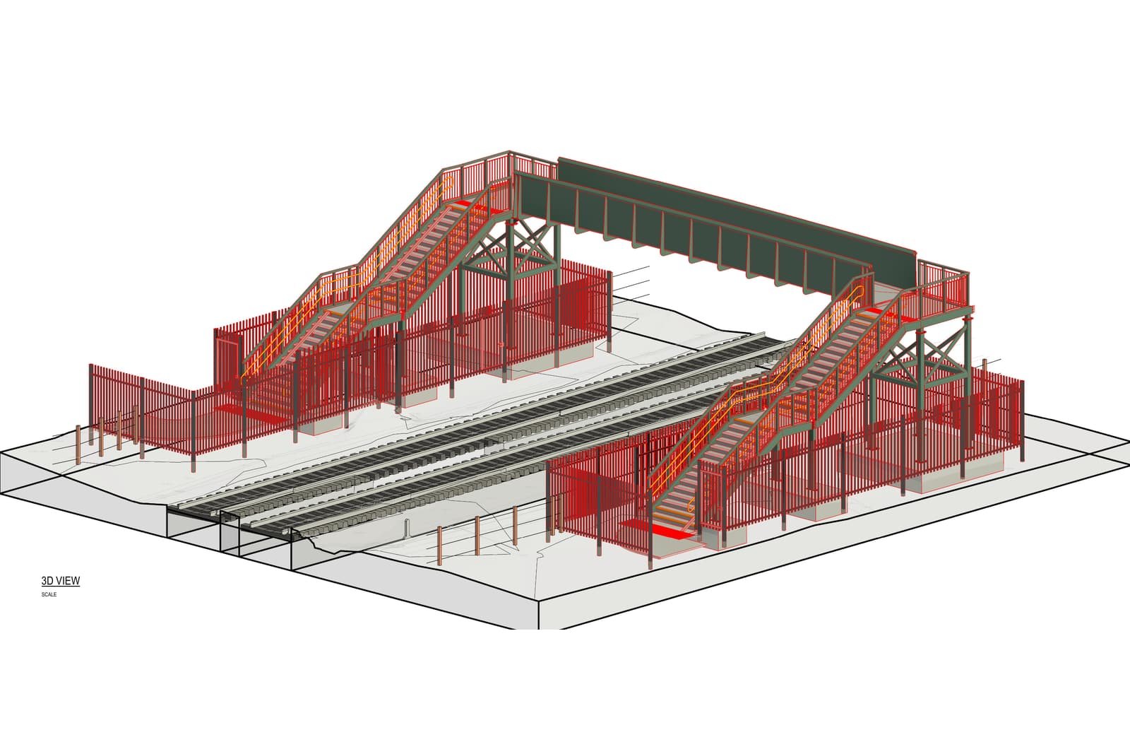
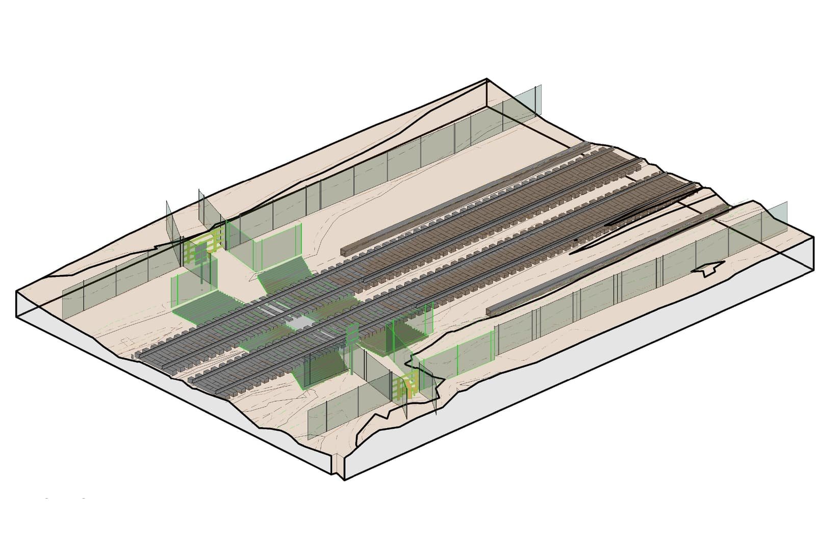
New Place: the proposed replacement footbridge, general arrangement. The superstructure was the known quantity from the start.
That is the pattern on nearly every non-station footbridge we deliver. The Technical User Manual (NR/CIV/SD/TUM/400) makes an honest promise: pre-approved steelwork, a shorter design programme, fewer detailing surprises. Contractors know it, and they price the steel accordingly. Where tenders get hurt is everything the TUM explicitly hands back to the scheme designer: foundations, clearances, ground improvement, OLE, temporary works, land and the approvals loop.
On a non-station footbridge, the superstructure is the known quantity. The risk sits in the site-specific scope. A designer who has done a dozen of them can turn that risk into a number at tender stage, rather than a variation at Form B.
What the 400-Series Actually Gives You
The facts first, straight from the TUM. The 400-series standard details cover single spans up to 28m between support centres, on trestle (SHS/RHS) or CHS supports, with stringer or truss staircases and ramps in flights of up to 6m at 1:20. Form A was signed in September 2013 and Form B, with a Category II check, in May 2015, so the superstructure arrives with its Approval in Principle and design approval already banked. Loading is 5 kN/m² pedestrian; fabrication is CE-marked to Execution Class 2.
Two things follow from that, and both matter commercially.
The standard drawings may not be redrawn or modified. Anything on your site that doesn't fit, a parapet extension, a deeper girder, a 180° stair turn on trestles, comes off the standard sheet and onto a bespoke drawing with its own scheme-specific F002/F003 submission. The moment that happens, you're no longer pricing a catalogue bridge.
The scheme designer still produces a site-specific F001, F002 and F003. The signed Form A and B cover the standard elements, not your site.
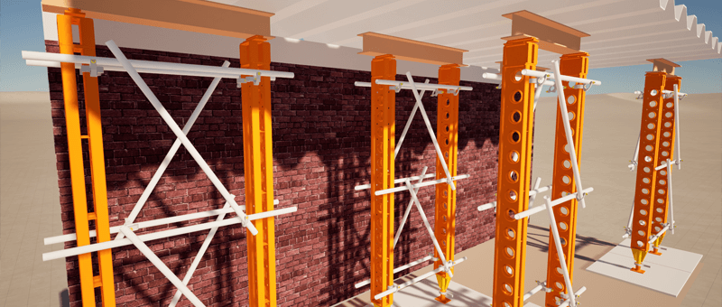
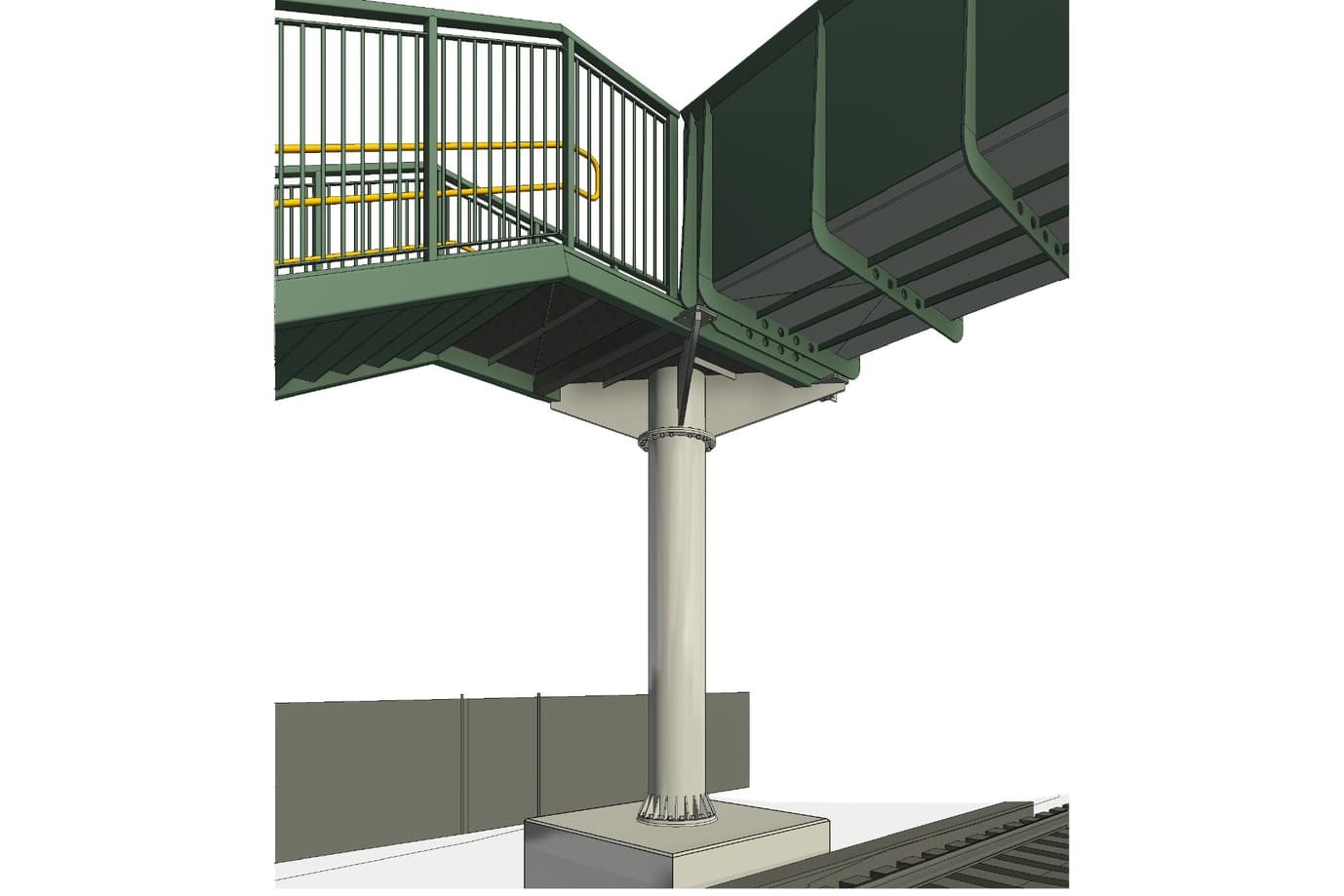
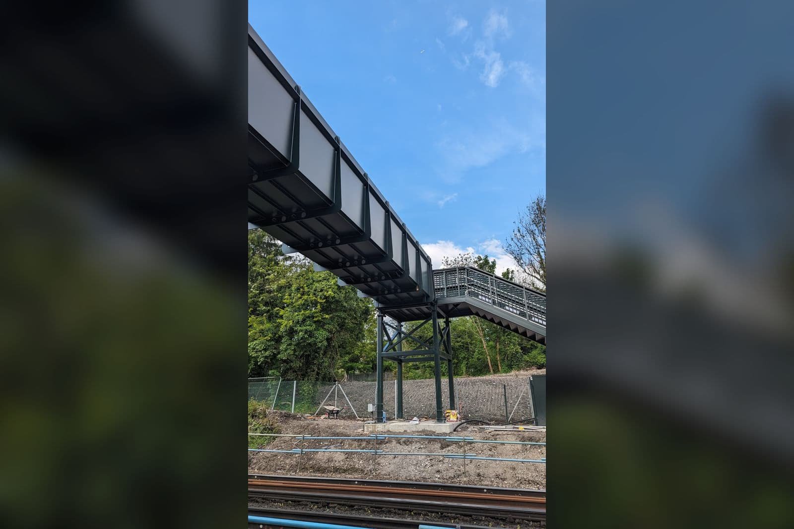
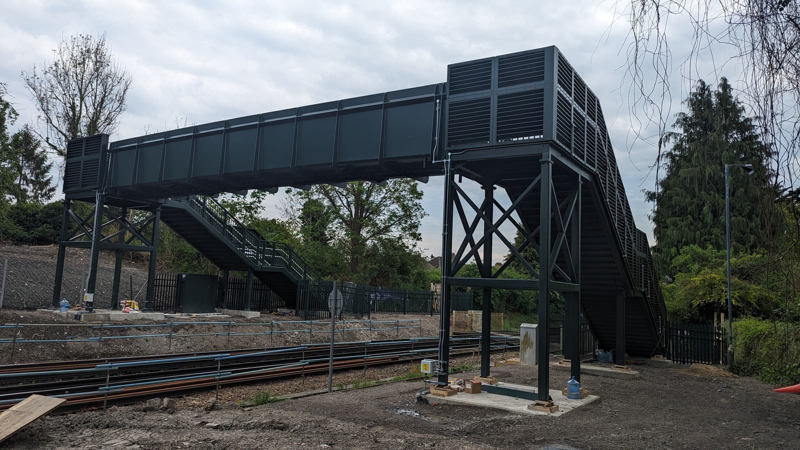
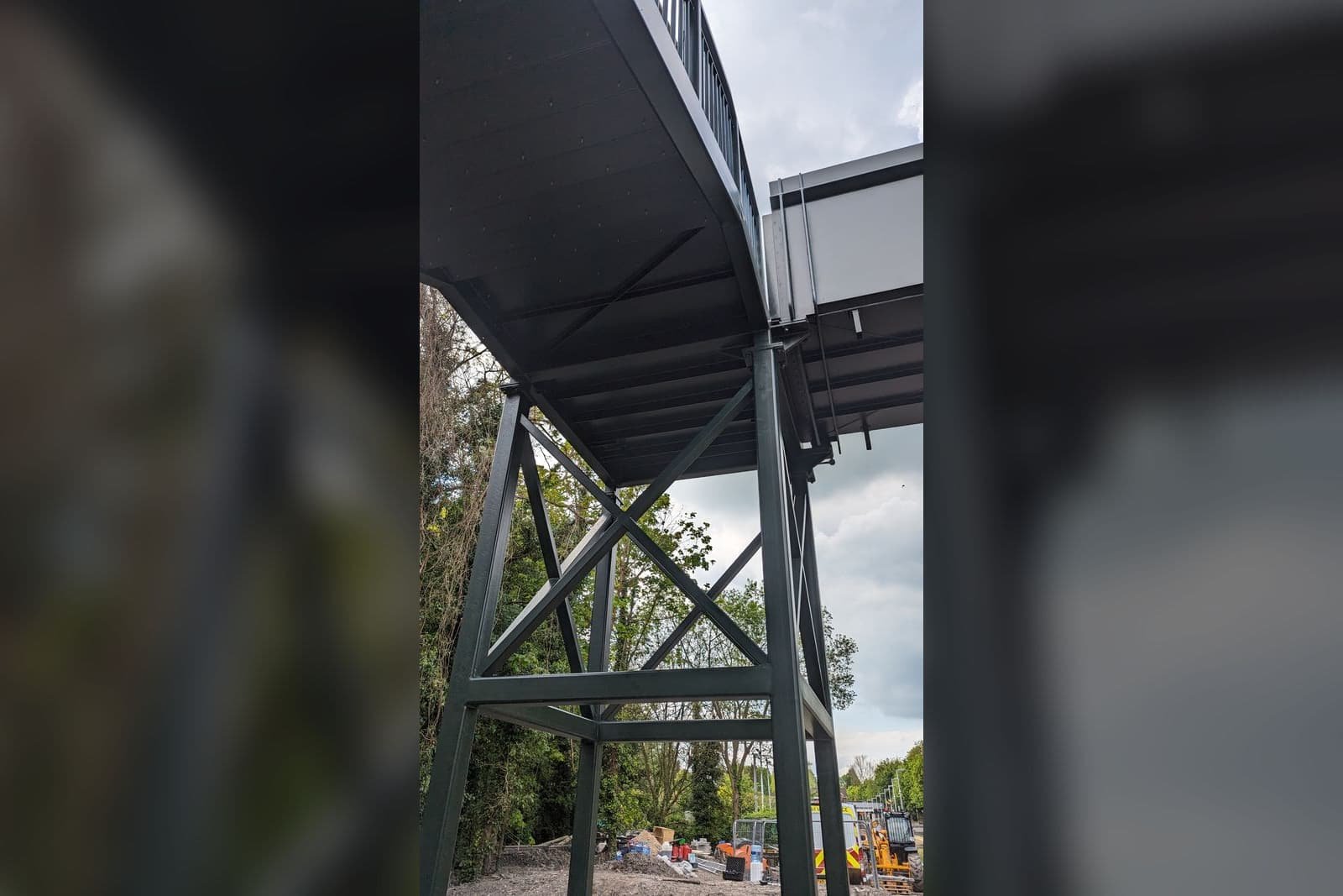
Standard support detail, fixed by the suite.
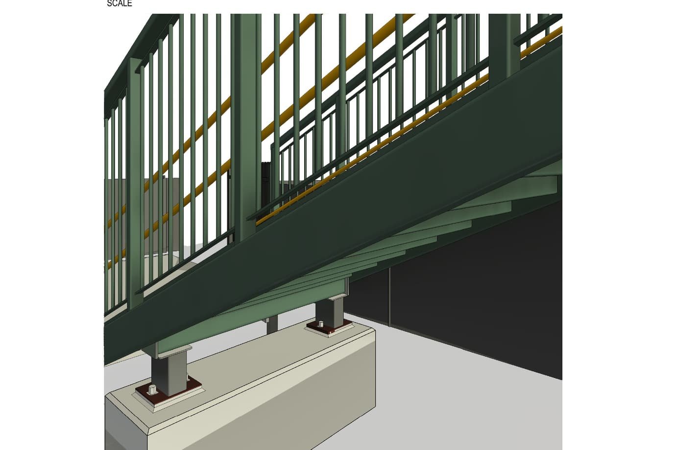
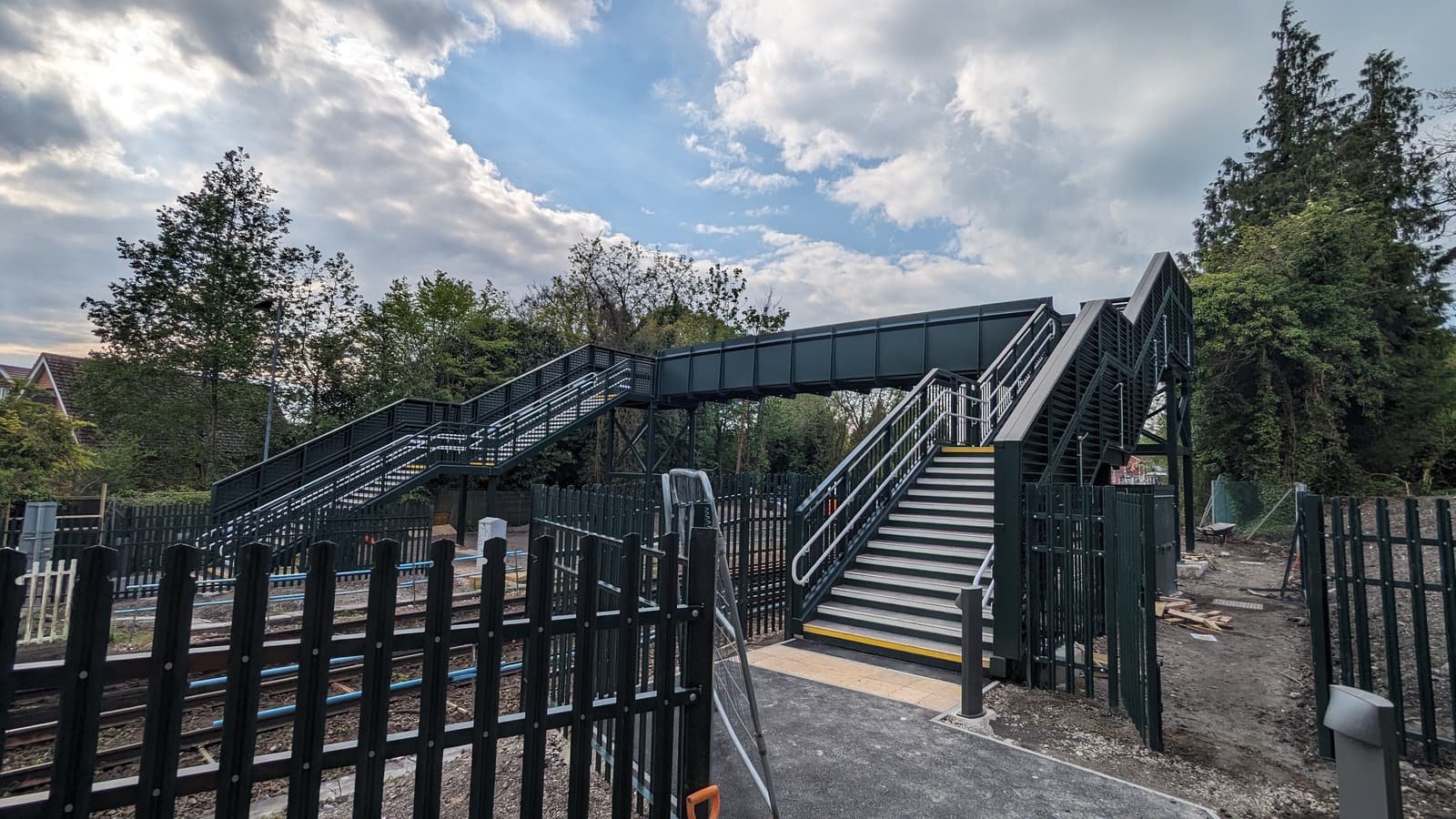
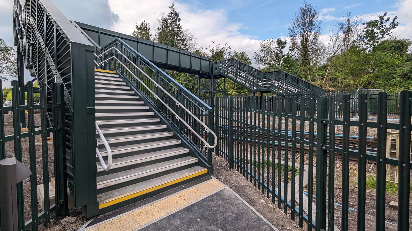
Deck and parapet, as drawn. Change either and it comes off the standard sheet.
There is also the 16m rural variant (Annex 3 of the TUM): steps only, trestles only, no MEP, no drainage system, no lighting. It’s a genuinely cheaper bridge, if, and only if, all ten of its limitations are met. We check the list before we let anyone price it. If one criterion fails, you’re back on the full 400-series and the saving evaporates.
The Seven Things That Move the Price
Across the crossing-closure and replacement schemes we’ve delivered, the variance between the tender number and the final account almost never comes from the steel. It comes from these seven items.
1. Foundations aren't in the standard details, at all
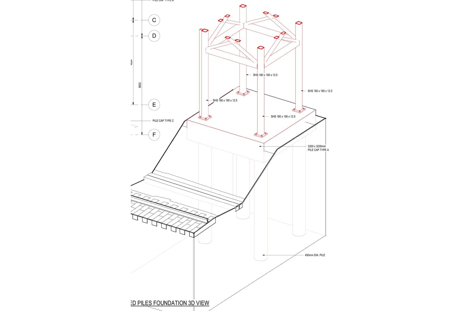
The TUM excludes foundation design entirely (§3, §7.3): it’s the scheme designer’s job, to Eurocodes, on site-specific ground. We’ve done piled caps at Pilgrims Way, piled through the Gault clay with a Category II check on the pile design itself, pad and plinth bases at Birch, and ground-improved bases at New Place.
The settlement limits are what make this bite: 20mm differential between main span foundations, 10mm between adjacent stair and ramp bases, 10mm horizontally. Those numbers are hard limits in the standard design, and soft ground doesn’t care that your superstructure is pre-approved. Our rule of thumb: if the desk study shows alluvium, made ground or a high water table, a borehole before tender costs less than the first week of a stalled Form B.
Pilgrims Way: piled caps, taken through the Gault clay.
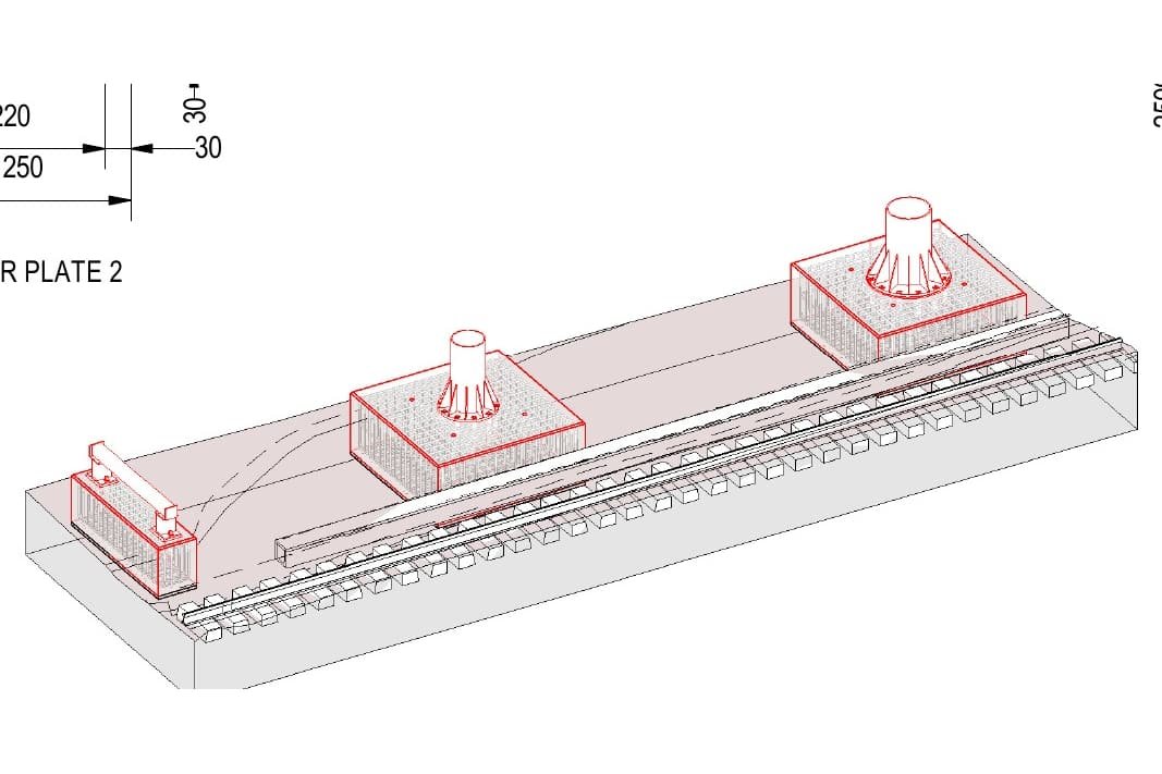
New Place: bases that needed ground improvement before the settlement limits could be met.
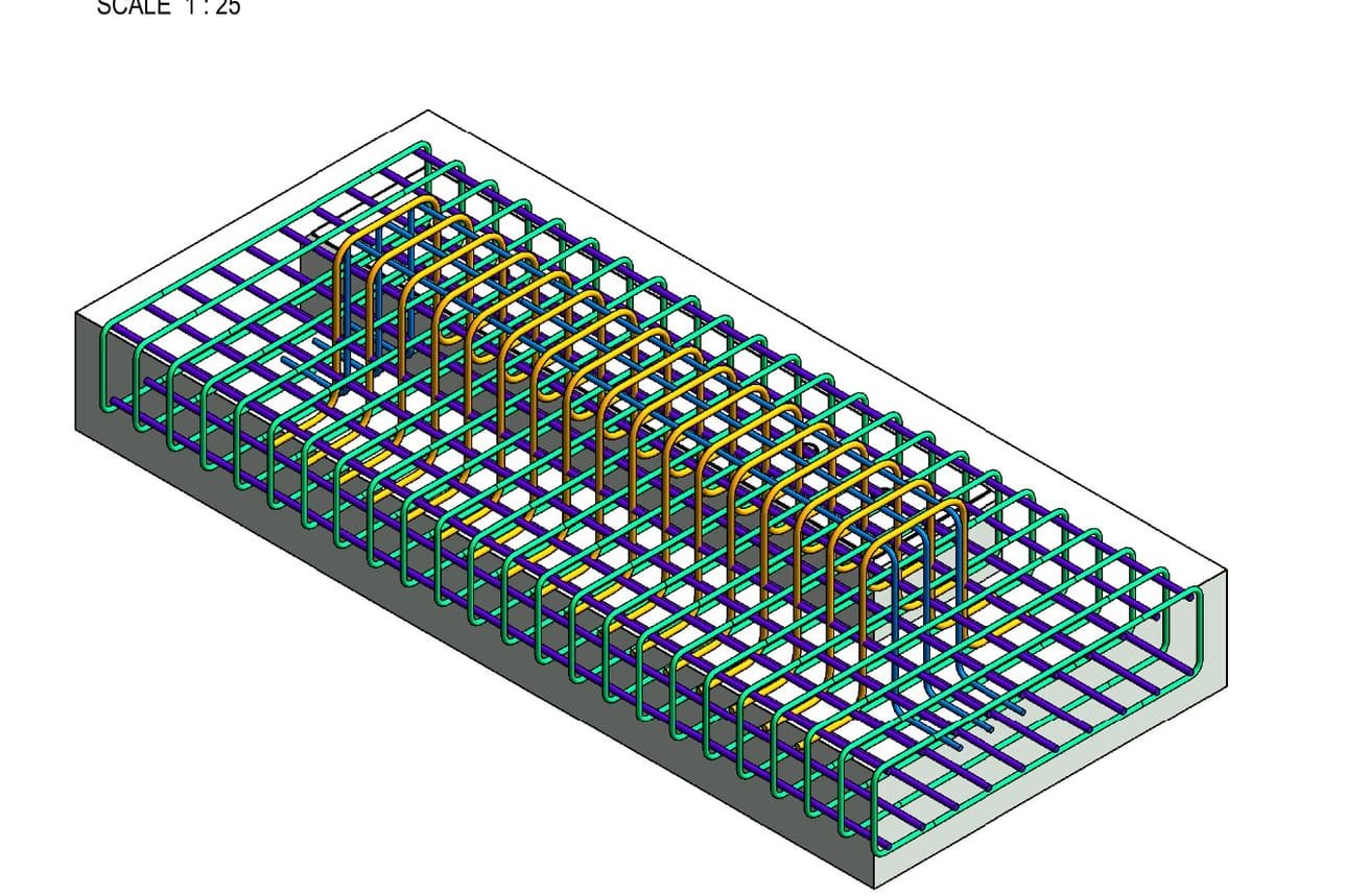
Reinforcement modelled in full, so congestion is found on screen rather than in the excavation.
2. The 4.5m rule
The standard details assume every support, measured to the trackside face of the stair stringer rather than the column, sits at least 4.5m from the nearest running rail. Inside that line you’re in the hazard zone, and the standard details are not designed for collision loading. Your options are a redesigned support that resists derailment impact, or separate protection, and either way it’s bespoke design and a bespoke price.
This is the single biggest hidden design item on tight sites. When the geometry simply doesn’t fit, structures start appearing that were never in the tender: the kingpost wall at Mount Street exists for exactly this kind of reason.
Mount Street: what tight geometry actually costs. Where the standard support positions will not fit, retaining structures appear that were never in the tender.
3. Vertical clearance and OLE
The standard suite works between a 5.1m minimum and a 6.3m maximum soffit above rail. Outside that envelope, the bridge is bespoke. And since GL/RT1210 replaced the old standard, the clearance from any standing surface to a live OLE part is 3.5m, which on electrified routes can quietly push a 5.1m soffit to 5.6m, with everything that does to stair rises, ramp lengths and land take.
Parapets over electrified lines go to 1.8m, which the standard details don’t cover: that’s scheme-specific design, again. And don’t assume a non-electrified route lets you off. Where a line may be electrified in future, the Route Asset Manager can still ask for the provision. Ask the question at AIP, not at Form B.
Soffit clearance is one of the fixed points the whole geometry is built around. Move it and the stairs, the ramps and the land take all move with it.
4. Wind governs the span the moment you add a canopy
Table 5 of the TUM is the table estimators should have taped to the wall. The headline 28m span applies without an anti-vandal canopy. With one, at a site wind pressure of 7 kN/m², the maximum span drops to 20.9m.
Canopies and anti-trespass screens also mean welded fixings. Retrofitting them later means site welding and reinstating the protective coatings, which is why the canopy decision belongs at AIP, not after the parish council writes in.
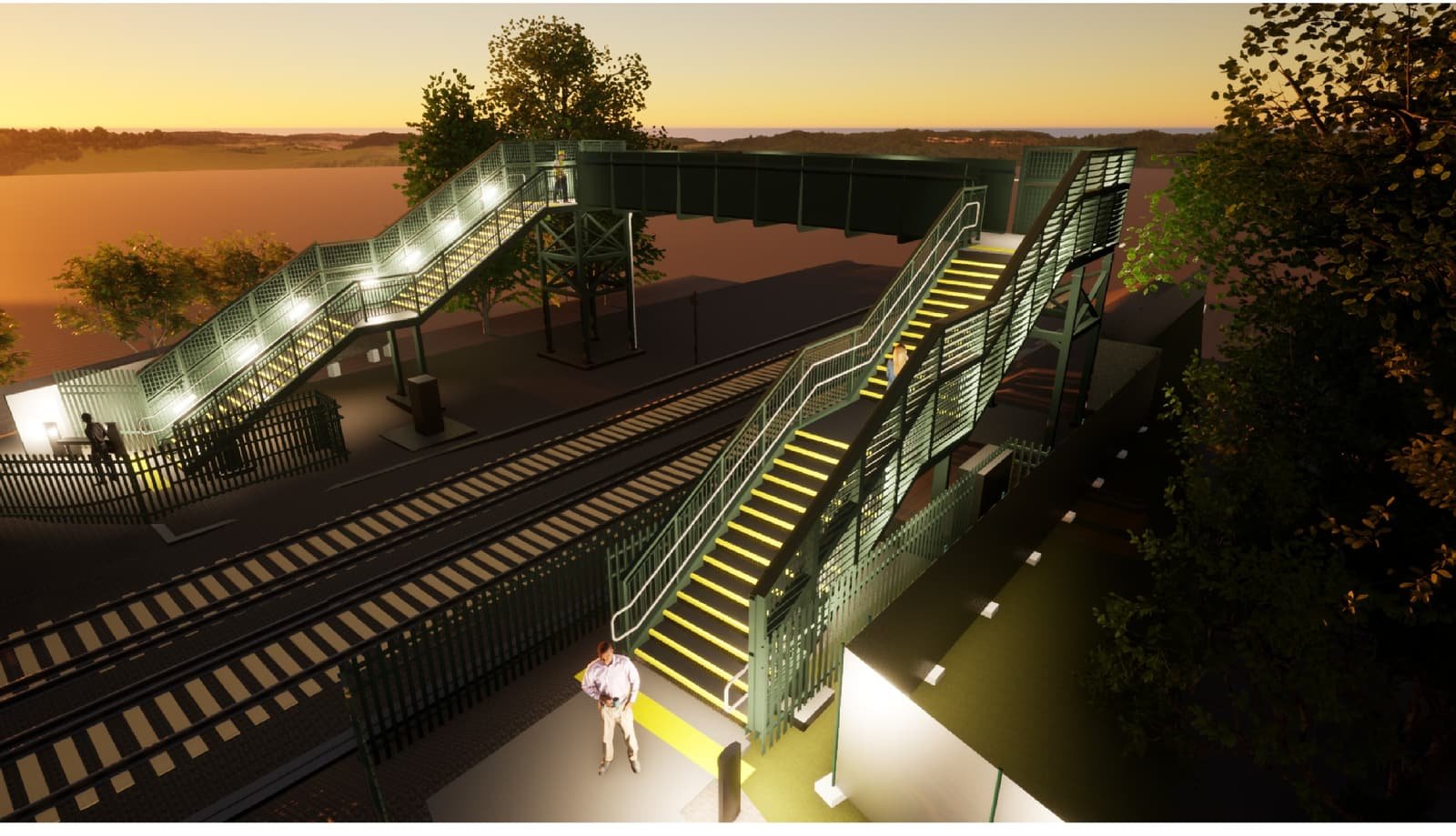
Daytime
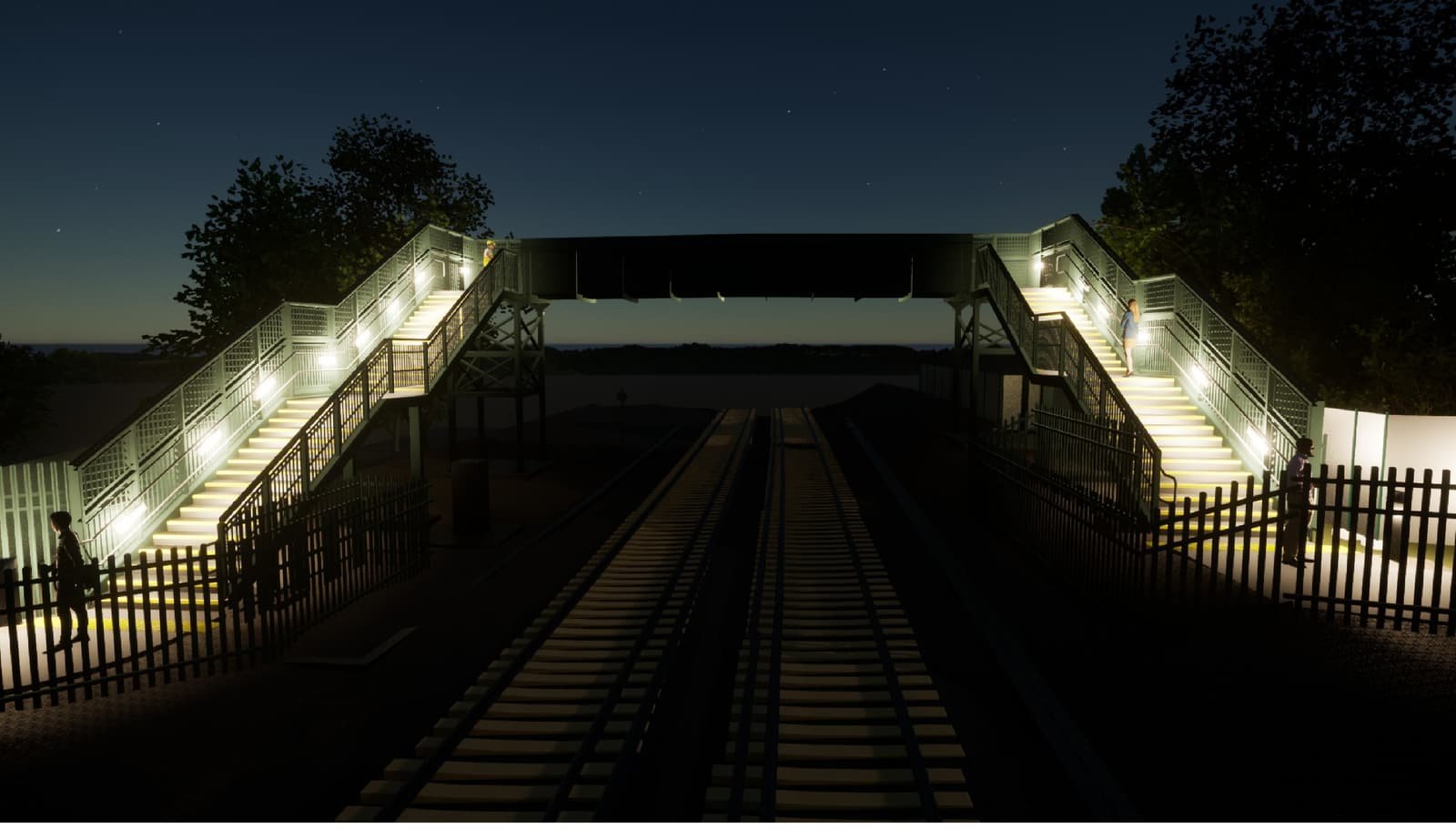
Dusk
After dark. Settling appearance, screening and lighting at AIP is far cheaper than answering the parish council later.
5. Temporary works are a design package in their own right
TUM §16 is one paragraph long and routinely worth six figures: temporary works on these schemes need their own F002/F003 and their own category check. Piling platforms (we produced the platform design at Pilgrims Way), crane outrigger pads (Birch, Weeley), temporary stability of part-erected structures.
Contractors regularly leave this out of tenders because it isn’t on any standard drawing, which is precisely the point: nothing site-specific is. Our temporary works team prices this as a defined package so it’s a line in the tender, not a surprise in month four.
Birch: pad and plinth bases.
Birch: foundations and crane positions planned together, because the lift decides where the bases can go.
6. Land, access and the crossing closure itself
Ramps at 1:20 eat land. Every metre of rise is 20m of ramp plus 2m landings, and it has to go somewhere. At Birch, the fee couldn’t be settled until a land purchase plan existed, because the ramp footprint ran beyond the railway boundary.
And where the footbridge replaces a level crossing on a public right of way, as at Pilgrims Way, Tallington and Birch, an F006 goes to the highway authority and BD29/17 applies, with its own views on risers, gradients and parapets. That’s a second approvals loop the TUM mentions only in passing, run by an authority that doesn’t work to Network Rail’s clock.
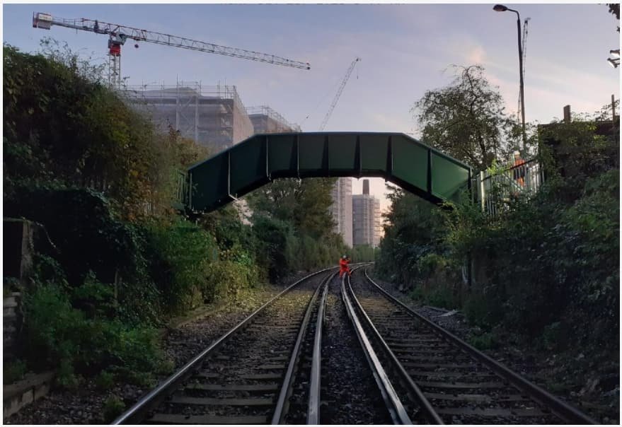
The existing crossing modelled from survey. Boundaries and levels decide whether the ramp footprint stays inside the railway land.
7. Services, ducting, drainage and bonding
The small print that’s expensive to retrofit. Four 125mm cross-ducts are built in at fabrication, welded through the structure and painted in the factory, not added on site. Drainage is galvanised steel with spitter pipes positioned so nothing discharges onto OLE or the running rails. Every element gets electrically bonded to NR/SP/ELP/21085, through faying-surface bolted connections or bonding straps.
Lighting is not standard on a non-station footbridge, but if the RAM or the planning authority wants it, that’s a lighting consultant producing its own F001 to F003. Each of these is small. Missing three of them isn’t.
The Approvals Loop Is a Programme Risk, Not Paperwork
The certification sequence on these schemes, Form A, IDC/IDR, Form B, DRN close-out, Form C and Form G, is usually drawn as an admin trail under the programme. On the schemes we’ve delivered it is the programme.
At Pilgrims Way, the critical path ran through DRN responses and interdisciplinary check actions, not drawing production; the record on that scheme shows the drawings waiting on the loop, never the other way round. New Place is the same story in miniature: revision P03 of the general arrangement is titled “NWR DRN comments”. The design was done; the loop wasn’t.
Two practical consequences. First, resource the responses: a DRN answered in two days keeps its slot, one answered in three weeks goes to the back of the queue. Second, and this is the one that catches design-and-build contractors, a Form G date written into a variation order is a contractual date the designer has to hit. Treat it like one when you tender.
Pilgrims Way from the air, with the working area still in place. The footprint a scheme needs during construction is rarely the footprint anyone allowed for at tender.
The Five Questions We Answer in a Tender-Stage Note
If you’re pricing a non-station footbridge, these are the five questions we answer for contractors before the tender goes in, usually in a short note, usually within a fortnight.
Does the site actually fit the standard details? Geometry checked against the Table 2 support height limits, the 4.5m horizontal rule and the 5.1m to 6.3m soffit envelope, and whether the 16m rural variant is genuinely available.
What are the foundations, and do we need ground improvement? Foundation type per support, settlement check against the 20mm and 10mm limits, and whether a borehole is worth buying now.
What does OLE do to the design? Soffit level after GL/RT1210, parapet height, screening, priced rather than assumed.
What's the temporary works scope? Piling platform, crane pads, temporary stability, as a defined package with its own approvals.
What's the realistic approvals programme? Form A to Form G, with the F006 and highway authority loop if a right of way is involved, and a Form B date you can put in the contract.
The steel is the known quantity. That’s the whole point of the 400-series. Everything else is where a tender is won or lost.
If you’d like that risk as a number rather than a hope, our bridge design team has the project records, Pilgrims Way, New Place, Birch and the rest, to price it from evidence. Talk to us before you tender.
Industry News & Education. In your inbox.
Join 3,000+ professionals who subscribe to our content.
READY TO START
YOUR NEW PROJECT?
Please fill in the form and we will get back to you as soon as possible to discuss your new project.